 "Urambo Tauro" (urambotauro)
07/09/2018 at 12:00 • Filed to: saab 900, project, wrenching
 3
3
 2
2|
"Urambo Tauro" (urambotauro)
07/09/2018 at 12:00 • Filed to: saab 900, project, wrenching | 3
| 2 |
One of the funny things about the Saab’s transmission being under the engine is that there’s no bell-housing to unbolt and use those holes to attach the engine to a stand.
So how does one put it on a stand at all? Well, it turns out that there’s a plate bolted to the rear of the engine, just like how there’s a timing cover on the front. (The rear of the engine is of course the clutch-end, regardless of the backwards engine orientation in the car. This is true with transverse engines too, but the way Saab has it turned 180° puts the front and rear terminology in more direct conflict with one another, and is more easily misunderstood.)
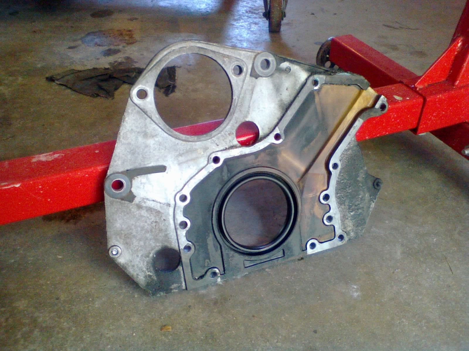
Anyway, this rear plate is necessary because it gives the starter motor something to attach to. It even has its own gasket where it mates to the block, sealing a channel where oil from the head is allowed to drain back down. The rear main seal seats in this plate too, as opposed to sitting in the block itself. With this end plate out of the way, we have access to several bolt-holes, which can be used to mount up an engine stand.
I took some measurements and hit up the local hardware store for some metric bolts. I would soon make another trip to pick up a 2" PVC coupler...
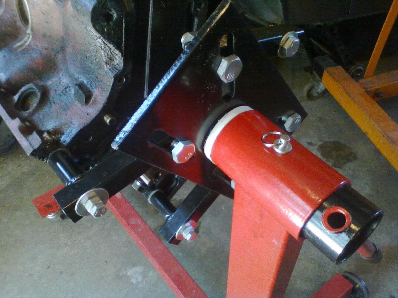
Once the head of the engine stand was bolted to the engine, and placed into the top of the engine stand mast, we could freely rotisserie the block. There was just one problem though- the holes for the locking pin didn’t line up quite right.
I had forgotten about this unfortunate side effect of buying a cheap stand. Whenever the pin is pulled to turn the block over, the head of the stand has to be pushed (slightly uphill) from its receiver to line the holes up again and lock it into position. I’m surprised I didn’t remember how frustrating this was from the last time I used it.
So this time I decided to do something about it. I measured the pipe, which was about 2-3/8". Turns out, that’s almost exactly the OD of 2" PVC. So I grabbed a coupler that would fit around it, and cut a spacer out of it (about 3/8" thick- that’s how far out of alignment the holes were) to fit between the mast and the head of the engine stand. Did some more trimming to make up for the weld bead, and finally got it to line up properly. So much better!
However, just like the head gasket overhangs the block to seal against the top of the timing cover, so must it overhang the block on this end to seal the top of the end plate. So, the head cannot be reinstalled until the block is back off of the engine stand, and the end plate and timing covers are put back in place. So the stand isn’t helpful for anything but bottom-end inspection/wrenching.
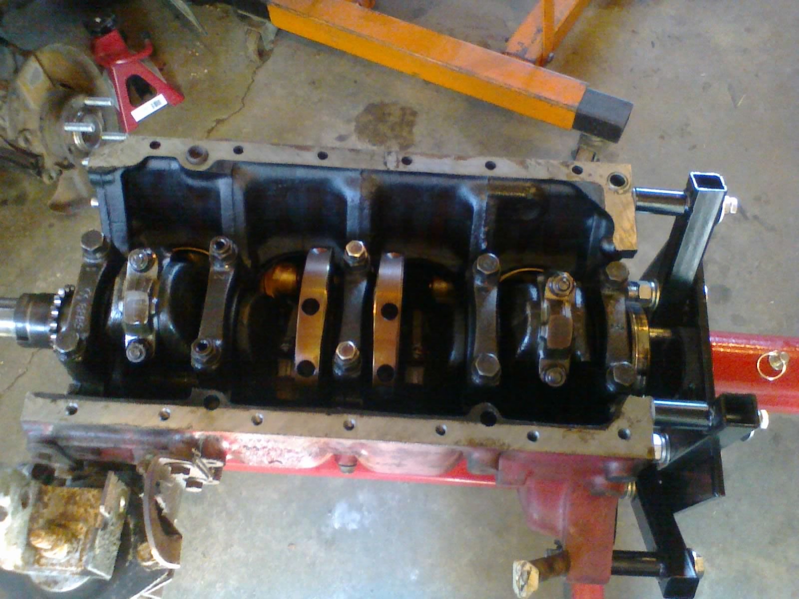
Speaking of which, we flipped the engine over, removed the oil pickup tube, and started inspecting the crankshaft bearings, one at a time, using Plastigauge. Every bearing had approximately 0.040mm of oil clearance , right in the middle of the 0.026-0.062mm spec (0.020-0.062mm for the rod bearings). Visually, they looked ok too, looking slightly polished with only a couple of super-light pits to speak of among the whole set.
Replace them now while we’re here
and reset the clock on their life expectancy? Or
wait until it’s time for full rebuild with rings and everything? It was a genuinely tough call to make, as there was some slight ring wear, but a
very much still-
visible crosshatch pattern... My brother finally decided to leave well enough alone. So maybe we’re not falling so deep into the might-as-well as we thought.
But what about that bearing play that I had mentioned !!!error: Indecipherable SUB-paragraph formatting!!! ? Well, it turns out that what I felt was actually just end play/float, which was also well within spec. So as soon as we inspect the head, we can start cleaning and reassembling things...
 pip bip - choose Corrour
> Urambo Tauro
pip bip - choose Corrour
> Urambo Tauro
07/10/2018 at 07:35 |
|
replace the bearings while the engine is out
|
Urambo Tauro
> pip bip - choose Corrour
07/10/2018 at 11:45 |
|
I’ll pass that along to my brother , but I’m pretty sure he’s made up his mind already.